home MEGACART Mk II Multicart tape restoration cartridge case news Mk I Multicart Mk 0 Multicart credits contact us buy
Section I: How to build the SC-3000 Survivors Mk I Multicart
Note - this is the original do-it-yourself Mk I Multicart tutorial. Please take a look - it is pretty cool. But if you're after the Mk II Multicart with packaged tape games and a menu system then click here.
We're going to build a SC-3000 Multicart that holds 32 (yes - thirty two) SC-3000 or SG-1000 games.
For those of you with a short attention span, here is the finished MK I Multicart in action.
Whoa! That's so cool! How do I make the SC-3000 Survivors MK I Multicart for myself?
This project is (reasonably) simple to build. You can do it with a few off the shelf components and fit it inside an existing SC-3000 or SG-1000 cartridge case.
We're going to take an old SC-3000 game cartridge, remove the existing ROM that the game is stored on, and replace it with a much larger EPROM which can hold 32 games plus some extra wires to a DIP switch to let you choose which of those 32 games to run. That's it. Sounds simple, eh?
The main reason why this build is so easy is that we are going to use an external EPROM programmer. That means we don't need any hardware to interface with a PC, and we don't need custom software to load the new games onto our cart.
Once upon a time this would have been very expensive, but right now you can buy a cheap EPROM programmer on eBay for $45 - $50USD including shipping, and a large 8MBit / 1MB EPROM for $7-$10 including shipping. And you can get a UV eraser (for when you want to change your games selection) for about $20USD on eBay including shipping. Those are the most expensive part of the build - everything else is cheap and easy to find. And the EPROM Programmer may come in handy for some later projects too :)
You will need some basic soldering skills. And if you don't have basic soldering skills, then this is the perfect time to learn! Some of the soldering work is a bit fiddly, and you may end up cursing a couple of times. But once you've had a bit of practice you will be able to build one of these real quick.
Disclaimer:
We take no responsibility for any damage caused to you, your property, your favourite cat, dog, pet bird, Uncle Bob, or Aunt May by the use or misuse of the information contained in the SC-3000 Survivors Multicart Project. We've done our best to come up with a project that is relatively safe and simple, but everything you do is at your own risk.
Contents
Overview - How / Why the Multicart works
You don't have to know how it works, but will make it a lot easier for you to troubleshoot any problems if you have a
vague idea what is going on.
Tools, Skills, and Components you will need
Build Sequence Checklist
Short summary of the build process - check this off as you go.
Overview - How / Why the Multicart works
How a SC-3000 games cartridge works Bank Switching / Memory Mapping / Paging How the SC-3000 Mk I Multicart Paging worksHome computers like the SC-3000 are simple enough that you can build one in your own garage. The SC-3000 Survivors MkI Multicart uses some old skool tricks and parts that have been around since the dawn of home computing. And with a bit of luck you will even be able to understand how and why it works.
How a SC-3000 games cartridge works
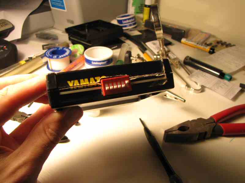
 Yamato Circuit Board
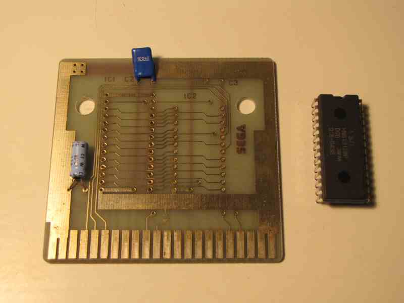
SC-3000 Games cartridges are very simple - they don't have much in them. Check out the following picture of a Yamato games cart.
There are only three components on that board. The 4.7uF electrolytic capacitor is designed to smooth out any major fluctuations in the power supply from the SC-3000. The 0.1uF ceramic or polyester capacitor is designed to decouple the ROM and smooth out any noise in the system caused by the rapidly changing voltage states at the ROM input and output pins.
The big black thing in the middle of the circuit board is the ROM chip that contains all the program code and screen data for the game. Almost all the SC-3000 games carts contain a single 28 pin ROM chip that holds either 16KB or 32KB.
The sole purpose of that circuit board is to supply that ROM chip with power and to connect the address and data lines from the Z80A CPU to the pins on the ROM.
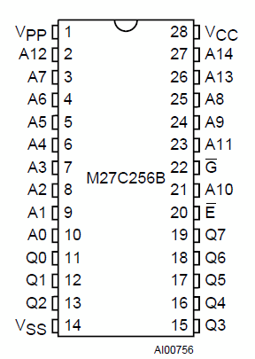 32KB ROM Pinout (256KBit)
The original 256KBit / 32KB ROM has 28 pins in total (see diagram). 15 of these are address pins - A0 to A14. That allows the SC-3000 to address all of the lower 32KB of memory space (0000 to 7FFF) in the ROM (as 2^15 = 32,768).
For example, say the computer needs to access the memory stored in position 14,297. That is 011011111011001 in binary. So the CPU just turns the voltage to the corresponding pins on or off. ie.
A5 = 0v, A6 = 5v, A7 = 5v, A8 = 5v, A9 = 5v,
A10=5v, A11=0v, A12=5v, A13=5v, A14=0v
Bank Switching / Memory Mapping / Paging
The Z80A is an 8 bit processor and only has a 16 bit address range. That means it can never directly address more than 64KB of memory. That wasn't a problem for the SC-3000 as all its games cartridges were 32KB or smaller. (Well, mostly anyway - there are a couple of ROM dumps floating around that are 40KB, but there are generally smaller versions of those games available, so we will ignore those). So the games carts usually just had a single ROM chip which was hard wired into the lower 32KB of memory, and the SC-3000 had 2KB of RAM located at the 48KB mark for storing temporary calculation results.
But newer 8 bit systems like the NES, the Sega Master System, Commodore C128, Amstrad CPC 6128 etc. soon needed more storage. They solved that problem with Bank Switching. Those systems could write out special instructions to a paging chip that would 'swap' part of the memory that the processor was connected to out to another portion of the ROM or RAM. Many SMS games, especially the later ones, required significantly more than 64KB to store all the game graphics and sound data, and each of these carts had a built in paging chip.
How the SC-3000 Mk I Survivors Multicart Paging works
The SC-3000 Survivors Mk I Multicart uses a very simple paging design (simpler than the SMS carts). We just swap out the bottom 32KB of memory space (0000 to 7FFF) to a different portion of a large 8MBit (1MB) EPROM. The 8MBit EPROM is 32 times larger than the original 256KBit / 32KB ROM, so we can fit 32 games on it. And because we are only paging or swapping out the lower 32KB of memory, we don't need to make any changes to the RAM access which is always in the top 32KB of memory from 8000 to FFFF.
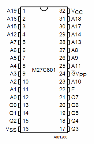 8MBit / 1MB EPROM Pinout
Our new 8MBit / 1MB EPROM has 32 pins in total. 20 of these are address pins - A0 to A19 (see diagram).
Now, see how the layout of the bottom 26 pins is identical to the original ROM? That lets the Sega control the bottom 15 address pins A0 to A14 as normal, but we control the +5v or 0v / GND signal to the A15 to A19 pins with a DIP switch.
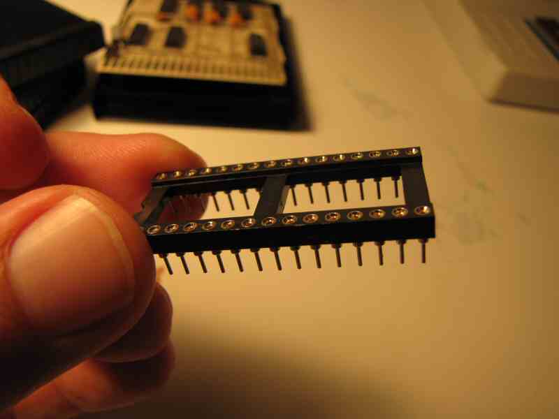
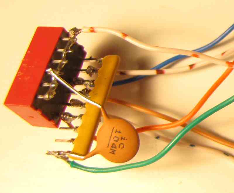
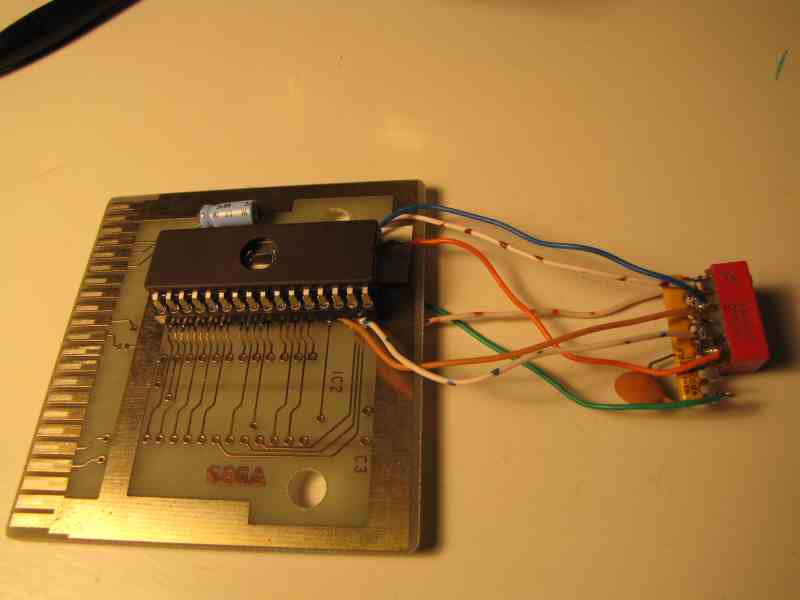 Completed Mk I Multicart with DIP switch connected to address pins A15 - A19
The DIP switch breaks the EPROM up into 32 distinct 32KB blocks and lets us map the base address 0000 to an arbitrary block within the 8MBit EPROM. One side of the DIP switches is connected to +5v, and the other side is connected to A15 to A19 and a pull down resistor network to force the logic level to GND or 0 when the DIP switches are open. When they are closed, it forces +5v or logic 1 at the relevant pin.
That's pretty much it. The only other changes we had to make to the original circuit board layout were to cut a couple of circuit lines that forced the A15 and A17 pins to +5v.
Tools, Skills, and Components you'll need
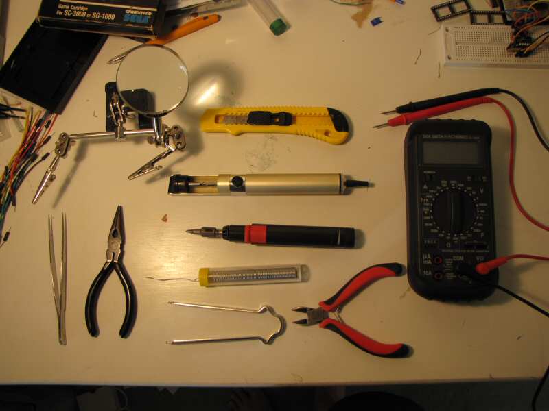 Various tools you will need
- soldering iron
- solder
- desoldering pump (solder sucker)
- desoldering braid / solder wick (not pictured)
- wire cutters / side cutters for cutting / stripping wires etc.
- long nose pliers and / or little tweezers
for grabbing little stuff :) - craft knife
for cutting a couple of lines on the circuit board and for shaping the hole in the cartridge case - blu-tack or mini work stand
for holding stuff in place whilst you solder - multimeter
Used for testing and troubleshooting
I won't say much about these. If you know what they are, then you probably have most of them already. If you don't know what they are, then click the links for more information and you can get them at any Electronics or Hobby store.
Skills - Soldering
Soldering is pretty easy to do once you've had a bit of practice. There are loads of good soldering tutorials around on the net, and I'm probably not the best person to teach you anyway :)
The two things I will say are:
- keep your iron tip clean and watch the video tutorial on tinning your bit halfway down this page
- soldering is easy if you have 4 hands. If you don't have 4 hands, then get yourself some blu-tack or a little work stand or both. That will save you a lot of hassle.
Check out these links for soldering hints and tips:
- http://www.aaroncake.net/electronics/solder.htm
- http://www.kpsec.freeuk.com/solder.htm
- http://www.smspower.org/Development/SMSReader-HowToSolder
The how to solder portion of the great SMS Reader tutorial
Components
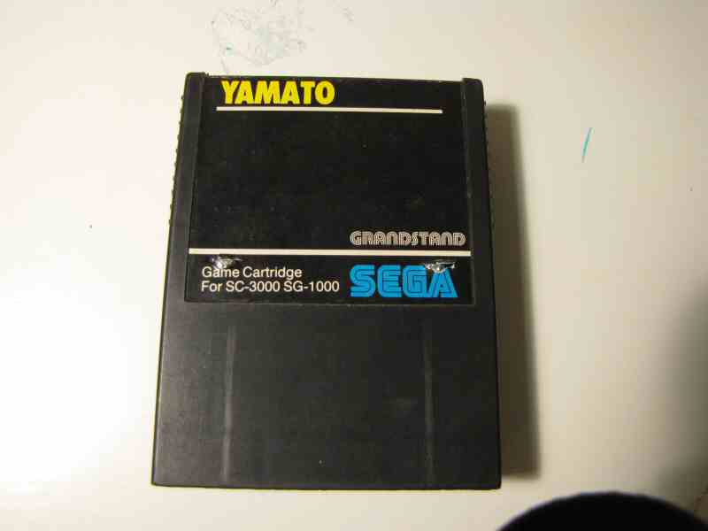 Yamato Cart
Donor cart
Free - just choose one you don't mind destroying :)
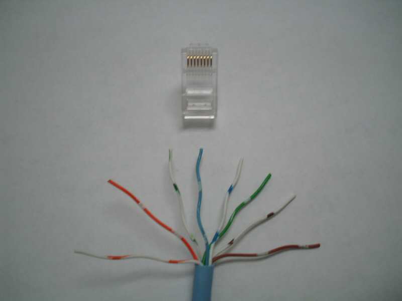 Cat 5 Ethernet Cable
Wire (eg. Cat 5 cable)
I just used Cat 5 Ethernet cable for the wiring in this project. You don't need much - 1 meter of cable is plenty. If you have an old cable hanging around then you can just cut the connector off the end and strip the individual wires out. Or you can buy some from a electronics store for around $1 / meter.
There is just one thing to be aware of - single core vs stranded wires. Single core wires are made from one piece of copper and stranded wires have several very thin pieces of copper twisted together. Both will work, but stranded wires are better suited to this project because they are more flexible than single core wires. You have to squish the DIP switch into place at the end when you assemble the cartridge. This is harder with single core wire, and you are more likely to accidentally break one of the joints you have so carefully soldered onto your socket. However you do need to take care that the strands don't come loose and cause a short circuit when you are soldering.
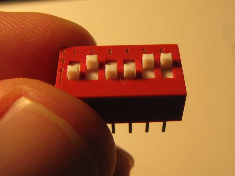 6 Position slider style DIP switch
6 position slider style DIP switch - $3
A DIP switch is just several little on / off switches joined together in a little plastic package. We are going to use the DIP switch to supply either +5v (on) or 0v / GND (off) to the top 5 address pins on our new, bigger EPROM. You only need a 5 position DIP switch, but I used a 6 position DIP switch because I might use that spare switch for something in a later project.
There are 3 main types of DIP switches: Slider, Piano, and Rocker. You want one that is easy to shift with your fingers. I used a slider style switch. A Rocker style switch could work well too, but you may need to glue the switch in place so you don't push it back inside the cartridge case when you change the switch positions. I would not use a Piano style switch - too fiddly. And do NOT get a DIP switch with recessed switches as you will need a needle or small screw driver to change the switch positions.
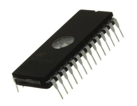 ST Micro 27C801 8MBit EPROM
8MBit / 1MByte UV Erasable EPROM
We are going to replace the existing ROM with an 8 Megabit (1 Megabyte) EPROM http://en.wikipedia.org/wiki/EPROM.
Look on eBay for 27C801 ST Micro EPROMs. These are going $6-$8 USD plus shipping on eBay. You can get two for $16 including shipping. Or $10 including shipping.
If you can't find that, then try a 27C080 Amtel 8Mbit EPROM
Note - you want the UV erasable EPROMs in a 32 pin ceramic DIP package. These are the ones with a little quartz crystal window that can be erased and reused. You can also get OTP (One Time Programmable) PROMs. Internally they are identical, but they come in a solid plastic package without the quartz window, so you can only write to them once.
 32 pin DIL / DIP Socket
32 pin DIL / DIP Socket
These are known as DIL (dual in line) sockets or DIP (dual inline package) sockets.
The socket makes it easy to insert or remove our EPROM whenever we want. I would buy a couple if I were you so you have a spare.
Important: Take a careful look at the style of 32 pin socket I have used. See how it has round pin holes? See how the round holder extends below the plastic frame? You're going to need one like that so you can trim some of the pins and solder wires to them without touching the circuit board below.
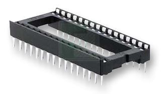 Do NOT use this type of Socket
Here is an example of a socket you do NOT want to use. These have little spring connectors instead of round holes. The problem is that the pins don't extend very far below the plastic socket body. So if you use one of these you will probably find it hard or impossible to trim the pins, solder wires to them, and still get the cartridge case to shut afterwards.
 Top853 Universal Programmer
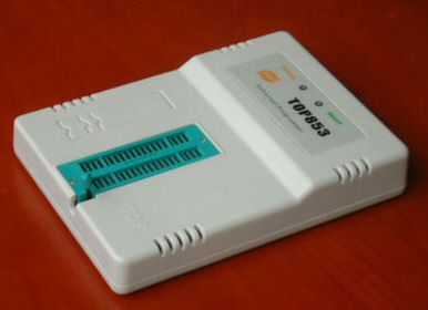
EPROM Programmer
This is a cheap Top853 Universal Programmer I bought off eBay for $35 USD + $12USD shipping. It works really well. The software supposedly runs on Vista and Windows 7, although I had to use XP because it doesn't seem to have 64 bit drivers for my 64 bit Vista OS.
 UV Eraser
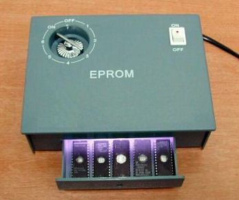
UV Eraser
Just buy yourself a cheap 'N nasty UV eraser like this off eBay for around $20. All you have to do is pop your EPROM in the eraser and set the timer to about 10-15 minutes. Then your EPROM is blank and ready for writing again.
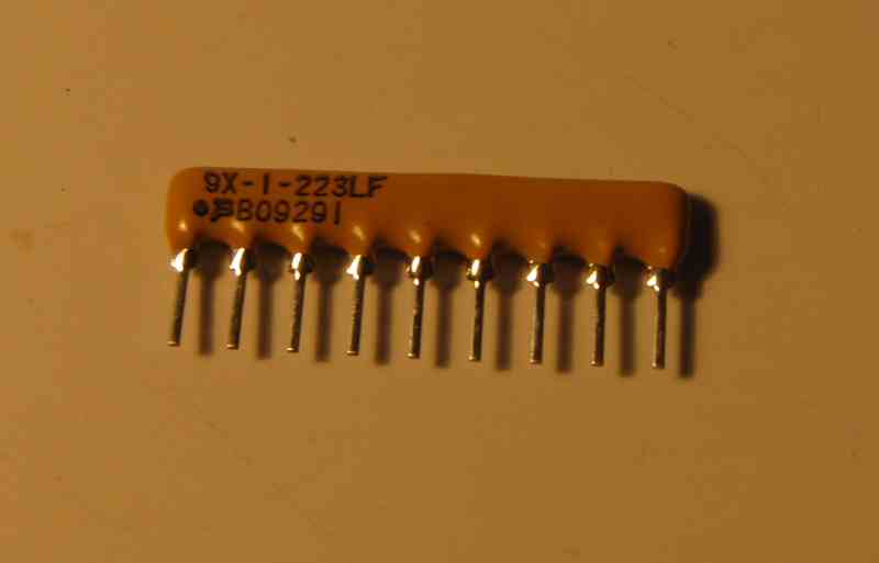 22K Ohm SIL Resistor Network
22K Ohm SIL Resistor Network $2
This ensures that pins A15 to A19 on our EPROM get a good clean 0v / GND signal when the DIP switches are open.
Spare 0.1uF ceramic capacitor, 16v to 50v - 50 cents
ROM images - Free
Just type sc3000 sg1000 roms into google and have a good hunt around :)
Build Sequence Checklist
Here's your quick summary that makes the build sound really easy. You should check this off as you go.
Part A - Prepare the EPROM and Multicart label.
Create your multicart EPROM image, burn your EPROM, and print out your Multicart label. You can do this at any stage, but after you've finally wired this beast up, it is nice to have your EPROM all ready to plug right in :) Just sayin.
You should print out your cart label now as you will need that during testing.
Part B - Build the Multicart
- Choose your Donor Cart
- Check donor cart AND SC-3000 both work BEFORE we start
There's nothing worse than spending a few hours on a project only to discover it was doomed from the start. - Open the cart (two Phillips screws)
- Remove the existing ROM
You will need a mixture of a solder sucker, desoldering braid, finesse, and patience :) - Review Board Layout / Hole and Pin Labels
These pictures explain which pins A15, A16, A17, A18, A19, and VCC are. - Remove the 100nF (0.1uF) capacitor from the board
Save it for re-use later unless you have a new one to replace it with. - Put tape down over the circuit lines that will run underneath your new 32 pin socket. This is optional, but it may save you a short circuit later.
- Prepare 32 Pin Socket - Trim pins
The circuit board was only designed to hold a 28 pin IC, and we are going to attach a 32 pin IC. Trim those extra 4 pins (A16, A18, A19, VCC) to fit your PCB. - Prepare 32 pin socket - attach wires to socket
Solder 5 x 8cm flexi-core wires to socket pins A15, A16, A17, A18, A19. Top two pin wires point towards top of circuit board, next two point left / right. Be careful not to short anything out. - Prepare DIP switch - attach +5v wire
Solder a single 10cm flexi-core wire to all pins on the OFF side of the DIP switch - Prepare DIP switch - attach network resistor
Solder 22KOhm Network Resistor to all the pins on the ON side of the DIP switch. Make sure that the common pin on the Network Resistor (marked with a dot) is off to the side. - Attach Socket wires to DIP switch
Attach 32 pin socket to the Network Resistor (ON) side of the DIP switch. Trim wires to size as you go. A19 goes to DIP1, A18 to DIP2, A17 to DIP3, A16 to DIP4, A15 to DIP5. - Attach 0.1uF to DIP switch and Network Resistor
Attach 100nF capacitor we removed earlier (or use a new one) between GND pin on network resistor and the middle of common 5v line across the OFF side of dip switch - Solder the 32 pin socket to circuit board
Solder the 32 pin socket (plus attached wires) onto the circuit board.
Remember you have to elevate it *just* enough so that you don't get a short circuit between the last 4 pins on socket and the circuit lines running underneath. But if you elevate it too much you won't be able to screw the cartridge case back together. It is a tight fit once the EPROM is in place :) - Solder +5v and GND wires from DIP switch to underside of PCB
Solder +5v wire from OFF side of dip switch to +5v / VCC on underside of circuit board. Solder GND wire from common pin on Network Resistor to GND on underside of circuit board. - Cut two lines on circuit board
The original circuit board forces pins A15 / A17 to +5v, but we want to control them from the DIP switch. - Test all connections with multimeter
It is important to do this thoroughly. It will save you hassle later, and should stop you from frying your SC-3000 if you have accidentally shorted something out. - Insert the new 8MBit EPROM into socket
- Test the FIRST Game on Multicart
Set all DIP switches to the OFF position. Plug the Mk I Multicart into the SC-3000 and turn it on. You should see the first game from your cart on screen. It should be the first game listed on the label you created earlier. - Test the LAST Game on Multicart
Turn the SC-3000 off. Set all the DIP switches to ON. Turn the SC-3000 on. You should see the last game from your label on screen. - Test a few other Games on Multicart
Turn Sega off. Choose a game from your Multicart label. Set the DIP switches to the positions for that game. Turn Sega back on. Check you get the game you were expecting. Repeat a few times. - Mark and cut hole in plastic case for DIP switch
- Reassemble Cartridge Shell and apply Label
- Done - Go Play some cool games
You now have your very own SC-3000 Survivors Mk I Multicart. Go have some fun - you've earned it.
Detailed Build and Testing Instructions
Completed Mk I Multicart with DIP switch connected to address pins A15 - A19
Remember - this is what we are trying to build. We're just going to remove the ROM from an existing cartridge and attach a new larger EPROM instead plus a few extra control wires running to a DIP switch. That's it. Simple :)
1. Choose your Donor cart
This is the one step where you might need a bit of help from us because if you choose a cart with a different circuit board layout then you may need a couple of minor modifications to the design. You can use almost any SC-3000 or SG-1000 cart, but some are better suited than others.
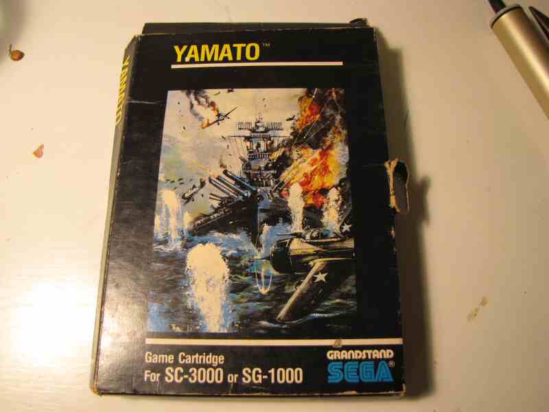
The donor cart for this project was Yamato. I have seen the same circuit board layout used for N-SUB, Sinbad Mystery, Star Jacker, and Congo Bongo. Look for a cart with all 44 pins on the cartridge edge connector and you have a good chance of finding this board (some have several pins missing on the B side or ROM side). Here are a variety of games cart circuit board layouts.

Any 32KB games cart *should* be fine. Most of the 16KB carts are ok too. But Sega used several different circuit boards for their carts, and you can't guarantee what you will find inside when you open up the cart as the local distributors in each country sometimes hacked the boards together themselves. Do NOT use the Champion Tennis cart (8KB ROM).
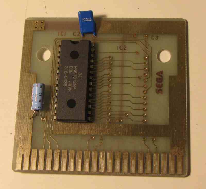 Side B - Top of Yamato PCB (component side)
If you can't find the exact same circuit board layout, then send us pictures of both sides of the circuit board you want to use and we may be able to make suggestions. Just make sure we can see all the circuit board lines clearly. In any case you should definitely read the "How it works" section because it is actually fairly simple to figure out what to change once you understand how the Multicart works.
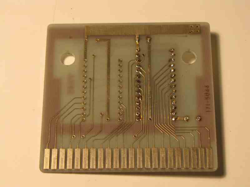 Side A - rear of Yamato PCB (solder side)
A Basic IIIA or IIIB cart will work just fine, but I highly recommend you use a games cart instead as it is a much simpler build. There is less room on the circuit board and inside the case, you will have to move a couple of capacitors, and there are plenty of other components to fry on the board. (See failed Mk 0 Multicart)
Note: You can NOT run Basic on the Multicart unless you use a Basic IIIA or IIIB cart because Basic requires the cartridge to have 16KB or 32KB of RAM on board.
2. Check donor cart AND SC-3000 both work BEFORE we start
Plug your donor cart into your SC-3000 to both it and the cart are working before we start. I wasted several days building my first Multicart on an empty Basic IIIB shell only to discover that it didn't work. I still don't know whether it was bust before I started, or whether I fried one of the components during the build. In any case, I could have saved myself a lot of pain by checking first.
3. Open your Donor Cart
Just unscrew the two Phillips head screws hiding under the sticker on the top of the cart and it should pop open.
Remember basic anti-static precautions
You can probably get away with just touching a grounded metal object like
a window frame before working with electronic components. That's all I've done for years. But for this project I bought
myself an anti-static wristband off eBay - it only cost $1 with free shipping. I don't know if it makes a difference or not,
but it makes me feel better :)
4. Remove the existing ROM
 Yamato board with original ROM removed
Remove the existing ROM and clean up holes with soldering iron / solder sucker / desoldering braid.
The thing you need most for this step is patience. At first you think you'll never get it off. But if you keep at it you will get it out in about 45-60 minutes. Or if you are willing to cut the ROM off then you can get the circuit board all cleaned up in around 15-20 minutes.
If you don't care about the original ROM, then you can cut the pins and quickly flick them out with your soldering iron / long nose pliers. Just don't cut too close to the board so you have something to grab. This is the quickest approach and has the lowest chance of you damaging your circuit board by overheating it. (If it gets too hot then the copper trace may start to lift of the board - that's bad. This technique is quicker, so the board contacts will be cooler.)
I wanted to save the original Yamato ROM to read it later just for interest. So I used a solder sucker to quickly suck up as much solder as possible, then the desoldering braid to get rid of the bits hiding down beside the pins. I then went around all the pins one by one they until started to come free. You then gently lever the ROM out with a screw driver, or IC tweezers. Just take care not to use too much pressure on the circuit board when you're trying to get the ROM out.
Here is an excellent tutorial I found on YouTube demonstrating how to cut an IC off your circuit board and how to clean up the holes with solder, solder sucker, and desoldering braid. If you haven't done this before then I highly recommend you watch the video in full - I found it very helpful.
More Desoldering Resources:
- Desoldering Tools
You don't need one of these for this project, but they sure make the job quicker.
Commercial Desoldering tools have a vacuum tube built around a heating element tip. So all you have to do is heat the joint and start the vacuum. I wish :)
You can get cheap desoldering tools like this $10.99 Radio Shack one. Or search on eBay for 'desoldering iron' for a variety of cheap alternatives. Just check the voltage - most of those are 110v / 120v, not 220v / 240v.
- Here's an alterative desoldering technique using a hot air gun. Looks easy, but I wouldn't try it myself.
- Just search for 'desoldering' on YouTube to see lots of different desoldering techniques
5. Board Layout / Hole and Pin Labels
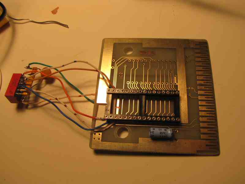
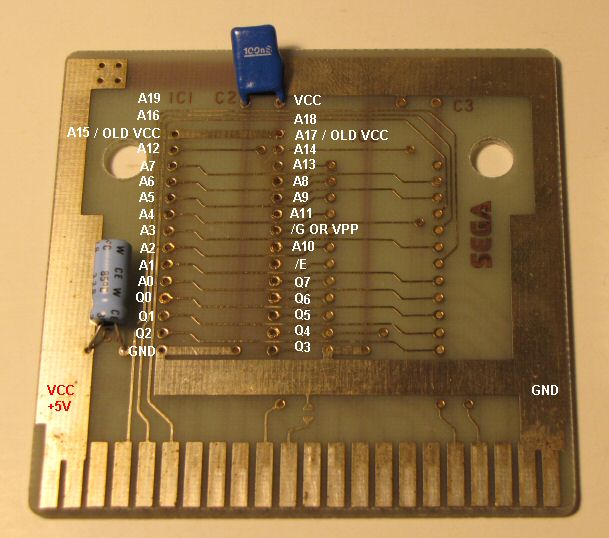 Side B (component side) - original Yamato ROM removed
Now that we have the ROM out, let's look at the labels for the holes on the board. I am going to use these labels during the rest of the build so use this for reference later on. And just remember - if you flip the board over, the pins are all reversed and it is easy to look at the wrong hole. You'll see what I mean once you have the board in your hand and turn it over a couple of times.
In our How it Works section we showed you how the original ROM has only 28 pins (link) and our new 8MBit ROM has 32 pins (link). I have overlaid the 32 pin layout of the new EPROM onto the circuit board (click the picture to enlarge).
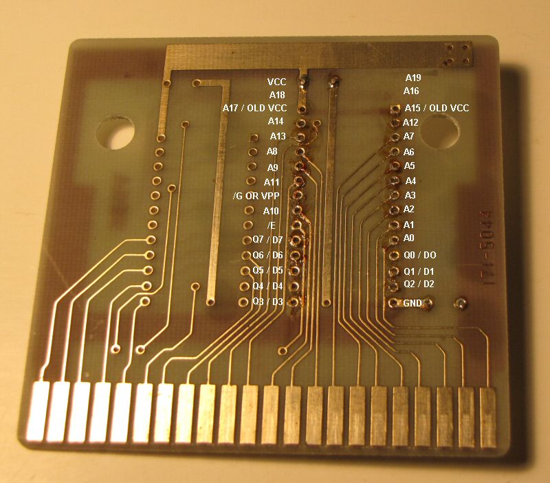 Side A (solder side) - Original Yamato ROM removed
I have also labelled the +5v feed (cartridge pins B01, B02) and the GND or 0v feed (cartridge pins B21, B22) from the cartridge connector. See how the +5v line runs up the left hand side of the front of the board (Side B) then jumps to the back of the board (Side A)? See how the GND line runs up the right side and along the bottom of Side B then jumps to the back of the board (Side A). You need to know where these are later on for testing purposes.
6. Remove the 0.1uF (100nF) capacitor from the board
Just heat up the solder and use your solder sucker or desoldering braid to quickly remove most of the solder. Then gently pull on the capacitor whilst applying a little heat to the remaining solder and it should pop out. You will need to save this for re-use later unless you have a spare 0.1uF (100nF) capacitor.
7. Put tape over the circuit lines
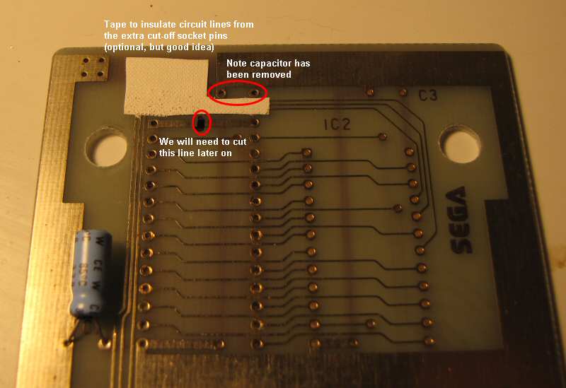 click to enlarge
Put tape down over the circuit lines that will run underneath your new 32 pin socket. This is optional, but it may save you a short circuit later.
8. Prepare 32 Pin Socket - Trim pins
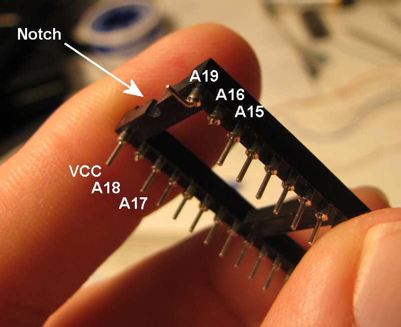
Remember to find the end of the socket with the notch. This always goes to the top. This is just a little visual reminder to make sure you always stick your EPROM in the right way up as the EPROM has a corresponding notch at one end.
The circuit board was only designed to hold a 28 pin IC, and we are going to attach a 32 pin IC. So we have to make those last 4 pins fit somehow (A16, A18, A19, VCC).
 click to enlarge
This step will vary a bit depending on the exact layout of the board you've used as a donor.
Check out the A16, A18, A19, and VCC pins on the photo to the right.
It just so happens that my new VCC pin fits perfectly into an existing hole on this circuit board which is attached to the +5v line. Sweet - no changes required. Your board may be different and you may need to trim this one also and run a short wire to a +5v feed.
The A16 and A18 pins will be sitting directly over the top of those circuit lines we just taped up, so they are trimmed nice and tight.
I decided to bend the A19 pin out instead of trimming it as that doesn't have any circuit lines under it. If I was doing the build again, I would trim it flush just like A16 and A18 because the extra height required by the time I attached a wire to it and some solder meant that the Yamato cartridge case doesn't *quite* shut properly. Dammit :)
9. Prepare 32 pin socket - attach wires to socket
 click to enlarge
Solder 5 x 8cm flexi-core wires to socket pins A15, A16, A17, A18, A19. Be careful
- No short circuits
- Don't hang low
- Don't flex wires too much or they may break off - hard to resolder later
- Point in different directions
Top two pin wires point towards top of circuit board, next two point left / right.
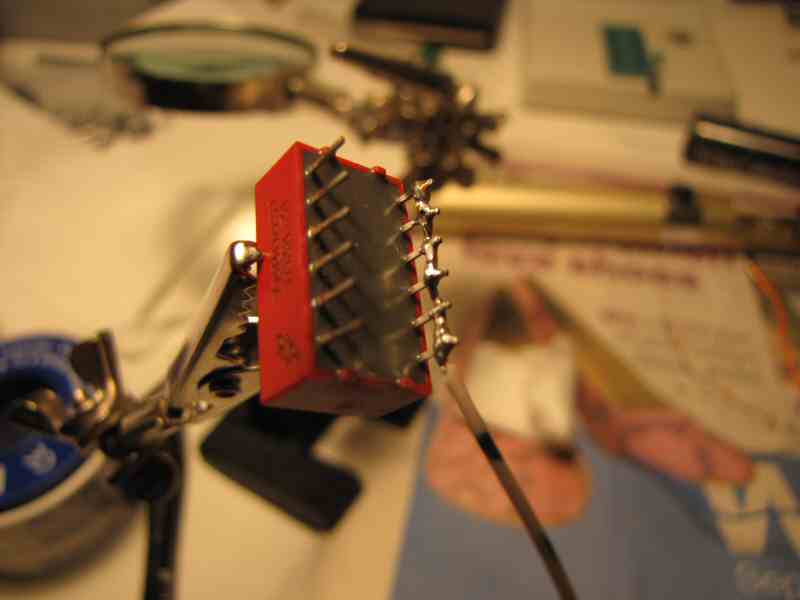
10. Prepare DIP switch - attach +5v wire
click to enlarge
Figure out DIP switch orientation. Hopefully you chose a slider style dip switch and hopefully it is nicely labelled with ON / OFF, and numbers for each switch. See how my one has each switch labelled as 1,2,3,4,5,6? I'm going to call those DIP1, DIP2, DIP3, DIP4, DIP5, DIP6 from now on.
 click to enlarge
Take a single 10cm flexi-core wire and strip the last 1-2cm. Loop this through all the pins on the OFF side of DIP switch array so the bare wire is touching all 6 pins.
Then solder the wire to all 6 pins
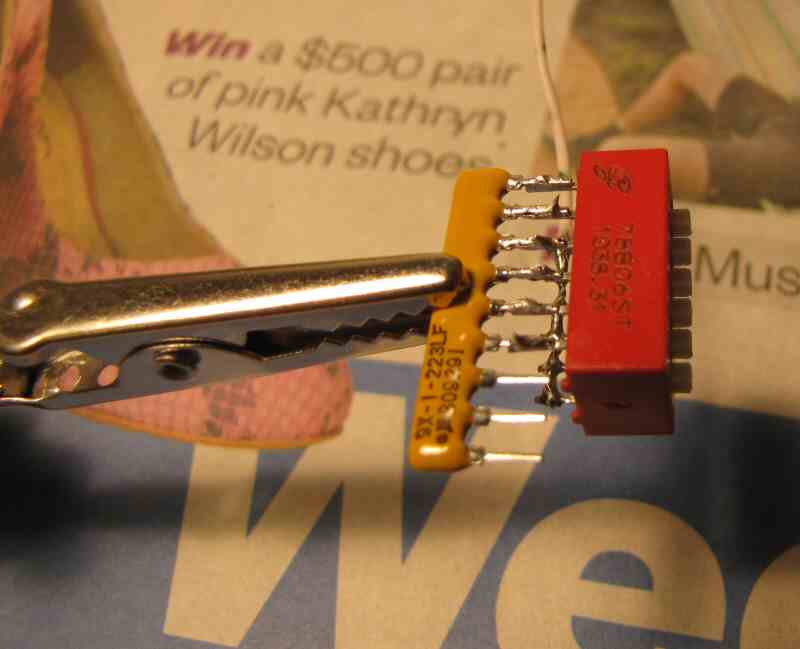
11. Prepare DIP switch - attach resistor network
 click to enlarge
Solder 22K Ohm resistor network to all the pins on the ON side of DIP switch array. Make sure that common pin on the Resistor Network (marked by a dot) is clear to the side.
Why do we do this? We are using this as a Pull Down resistor. This ensures that we get a nice clean GND or 0v when the DIP switches are in the OFF position.
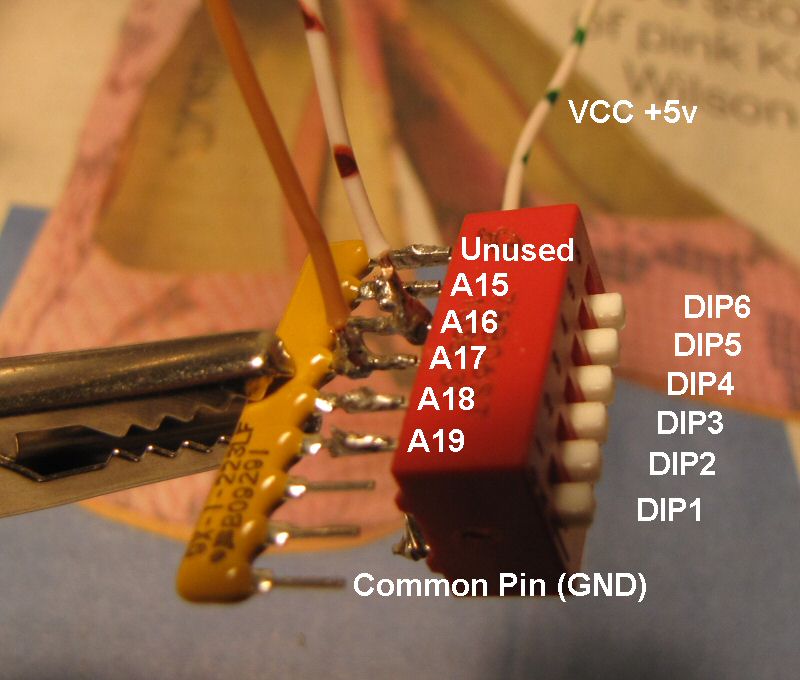
12. Attach Socket wires to DIP switch
 click to enlarge
Attach the wires from the 32 pin socket to the Network Resistor (ON) side of the DIP switch. A19 goes to DIP1, A18 to DIP2, A17 to DIP3, A16 to DIP4, A15 to DIP5.
 click to enlarge
Think about where the DIP switch is going to poke out of the case (see step 22 LINK) and trim the wires to size as you go leaving only a couple of cm of slack. I chose to poke my DIP switch out the top of the case (see following picture of completed multicart), but you might prefer the sides.
13. Attach 0.1uF to DIP switch and Network Resistor
 click to enlarge
Add the 100 nF (0.1uF) capacitor we removed earlier between the GND pin of network resistor and the +5v side of DIP switch. You can see I have used a new 0.1uF ceramic capacitor instead of the original one.
Why? For decoupling purposes
14. Solder the 32 pin socket to circuit board
Solder the 32 pin socket (plus attached wires) in onto the circuit board.
Remember you have to elevate it *just* enough so that you don't get a short circuit between the last 4 pins on socket and the circuit lines running underneath. But if you elevate it too much you won't be able to screw the cartridge case back together. It is a tight fit once the EPROM is in place :)
15. Solder +5v and GND wires from DIP switch to underside of PCB
 Your board should look something like this
This step will vary a little depending on the exact circuit board you chose as your donor cart.
Solder +5v wire from OFF side of dip switch to +5v / VCC on underside of circuit board
Solder GND wire from common pin on Network Resistor to GND on underside of circuit board.
 Rear view showing where DIP switch +5v and GND lines are soldered to circuit board
16. Cut two lines on circuit board
 Line to cut - Front
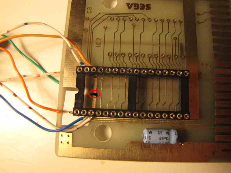 Line to cut - Front
The original circuit board forces pins A15 / A17 to +5v, but we want to control them from the DIP switch. So we have to cut the lines on the circuit board that join A15 / A17 to +5v. This step may vary depending on which circuit board you chose as your donor, but the chances are those two pins will still be forced to +5v and you will need to cut something.
Use a sharp craft knife to cut the line a few times in one place. You then may then want to use a small screwdriver to lever up a tiny bit of the circuit trace just to make sure.
Important: Try really hard not to slip. You don't want to cut or damage anything else on the circuit board, or your fingers :)
 Line to cut - Rear
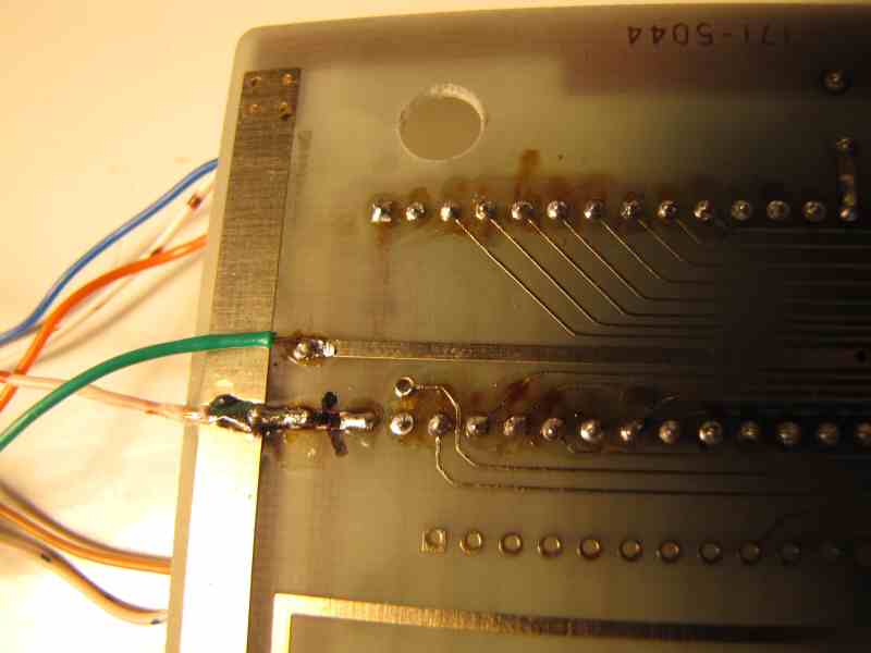 Line to cut - Rear
17. Test all connections with multi-meter
It is important to do this thoroughly. It will save you hassle later, and should stop you from frying your SC-3000 if you have accidentally shorted something out.
Watch the following video on how to do it. That is easier than trying to explain how to test everything.
Here's the checklist I follow in the video:
- Set all 6 DIP switches to OFF
- Make sure no shorts between +5v and GND
- Check for continuity between VCC and +5v
- Check for 22KOhm resistance between A15 to A19 and GND
- Set all 6 DIP switches to ON
- Check for continuity between A15 to A19 and +5v
Advanced Troubleshooting Tips
Check out the last bit of the video. Also Pinout chart for the cartridge connector and labelled image?
18. Insert the new 8MBit EPROM into socket
Insert your new 8MBit EPROM containing your chosen 32 games into the socket. That sounds simple - and it is. But it can also take a bit of practice. Check out the video clip below for some hints and tips.
Your completed board plus EPROM should look something like this
The most important thing to do is to make sure that your pins line up with the socket before you try to push it in.
The socket is likely to be a bit stiff to start with and the EPROM pins are unlikely to line up without some adjustment. Watch the video - I managed to stuff that up on camera for you and bend a pin :) I fixed it though.
19. Test the FIRST Game on Multicart
Ok, hopefully your Mk I Multicart is ready to rock now. So now is a good time to remind you about our disclaimer before you plug it into your SC-3000 :)
Important: Always turn the SC-3000 power off BEFORE changing the DIP switch positions. Failure to do so will result in unpredictable behaviour at best and may damage either the Multicart or your SC-3000.
Set all DIP switches to the OFF position.
Plug the Mk I Multicart into the SC-3000 and turn it on. You should see the first game from your cart on screen. It should be the first game listed on the label you created earlier.
Troubleshooting Tips:- If you get a game, but just not the one you expected, then you've either created the ROM image incorrectly, or you have mixed up the wiring from A15 to A19 to the DIP switch. Try to figure out which :)
- If you don't get anything loading on screen, then turn the SC-3000 off, remove the cart and gently reinsert. Turn power back on again. Repeat a couple of times.
- Try a known good cart and make sure that still works.
Consider cleaning your SC-3000 cartridge port. This is simple to do and makes a big difference to how easy it is to plug a cart into your Sega.
Here's a good YouTube clip showing how to respring / clean the cartrige port contacts on a Sega Master System. The cartridge edge connector springs on the SC-3000 are similar, so just use the same technique.
If your cartridge port is really dirty, you might need the white T-Shirt cleaning trick. Just remember that water and electricity do NOT mix, so watch the video in full.
- Look at the screen display and listen to the sound your TV is making. Hopefully it just looks and sounds like a badly inserted cart. If you've spent any time with SC-3000s then you know what I'm talking about :) What you don't want is something that feels quite different - eg. A hum or moving interference pattern on screen instead of a reasonably static dark picture. That might indicate some sort of subtle wiring fault or faulty bypass capacitor. Go back and re-check all the previous instructions, testing, and wiring.
20. Test the LAST Game on Multicart
Turn the SC-3000 off. Set all the DIP switches to ON. Turn the SC-3000 on. You should see the last game from your label on screen.
Troubleshooting Tips:- If you get a game, but just not the one you expected, then you've either created the ROM image incorrectly, or you have mixed up the wiring from A15 to A19 to the DIP switch. Try to figure out which :)
- If you just get a blank screen, then you may not have written to the entire ROM - check the size of your ROM image file.
21. Test a few other Games on Multicart
Turn Sega off. Choose a game from your Multicart label. Set the DIP switches to the positions for that game. Turn Sega back on. Check you get the game you were expecting. Repeat a few times with different games.
22. Mark and cut hole in plastic case for DIP switch
You can see I chose to poke the DIP switch out the top of the case. This keeps it clear of the new label on the front of the cart and clear of the circuit board. Plus most of the wires from the circuit board are a similar length and don't have to bend much which feels like a good design choice (although probably doesn't make any difference). Feel free to poke it out somewhere else - just think carefully before you start cutting and make sure you will be able to shut the case afterwards.
You can glue the DIP switch in place if you want, but I chose not to. I want to be able to easily open the cart again later when I want to update the EPROM. The tension in the wires actually seems to hold it in place quite well. If I was going to glue it, then I would only glue the DIP switch to the bottom half of the case.
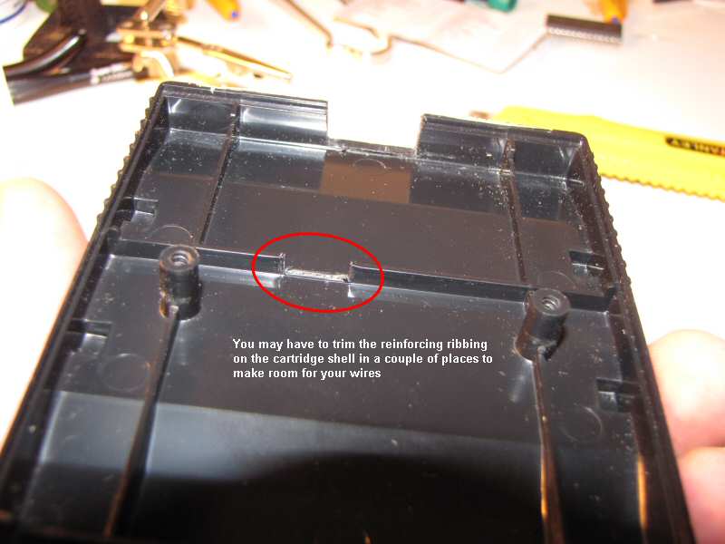 you may need to trim the reinforcing ribbing on case - click to enlarge
23. Reassemble Cartridge Shell and Apply Label
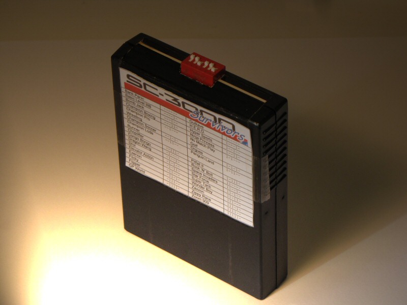 The Completed SC-3000 Survivors Mk I Multicart
Tape the label we printed out in step 1 to the front of the multicart showing all the games and DIP switch positions. Don't glue it for now because you may want to change the games stored on the EPROM later on and then you can just print out a new label. Print out and apply sticker with cart names / dip switch positions.
24. Done - Go Play some cool games
Play those games, and rewrite the EPROM if you aren't happy with your selection. There are around 80 SC-3000 and SG-1000 carts available, so you could get yourself a couple of spare EPROMs and either make up another Multi-cart, or just swap the EPROM in / out when you want to play a different set of games.
Preparing the EPROM image and Multicart Label
I've thoughtfully created a video showing you how to use the HxD Hex Editor to create your ROM image containing 32 SC-3000 games.
Here's a summary of the video for you
- Find some SC-3000 and SG-1000 ROM images
Just go to Google and type something like
download SC 3000 ROM images SG 1000
Hunt around and you should find them. Them are often grouped with Sega Master System ROMs
- Copy the 32 ROMs that you want into a new folder
You'll see why in a minute. We may have to modify some of them slightly or rename the files. - Rename your ROMs so they appear in alphabetical order
Just use Windows Explorer to rename the filenames. Some of the ROM downloads are likely to have names like "SG1000_CongoBongo.sc" etc. Just rename to something like CongoBongo.sc
- Check File Sizes. Discard any ROMs over 32KB in size and be prepared to modify any smaller than 32KB in size. We are going to just append all these ROM images together, so they have to be exactly the right size.
- Download HxD from http://www.mh-nexus.de/
Open any small ROMs in HxD to make them bigger. For each small ROM:
Ctrl-End
Edit->Insert Bytes
4000 hex bytes for 16KB ROMs, 6000 hex bytes for 8KB ROMS
Fill FF
Save File. Close File.
- Do a paranoid file size check.
Highlight all 32 ROMs in Windows Explorer. Properties. There should be 32 files and 1,048,576 bytes in total. If not, then one or more of the files is the wrong size. Check the file properties one by one. Each individual file should now be 32,768 bytes long.
- Concatenate all the files together in HxD
Extras->File Tools->Concatenate
Select all the roms, reorder as required
Output FileName First32Roms_Concat.bin - Right click on our new First32Roms_Concat.bin file. Properties. That should be 1,048,576 bytes it total.
- Create the label using our handy MK I Multicart Label Word Document. Just fill in the label in alphabetical order, or the same order you appended your ROM images together in.
- We are ready to burn our image onto our new 8MBit EPROM.
Burning the EPROM
This step is going to vary depending on your particular EPROM programmer. Here are a few quick snaps from writing with my TOP853 programmer ($47 USD on eBay including postage).
Sorry - looks like I didn't get around to taking these screenshots. But it shouldn't take you long to figure out. From memory with the Top853 the process runs something like this:
- Install the TopWin6 Software (32-bit windows only)
- Make sure you have a blank EPROM. If not, then stick it in the center of your cheap UV Eraser and wind the dial around to just past the number 1. That should give it about 10-15 minutes, which seems plenty.
- Insert your blank EPROM into your Programmer. Make sure you align the notch at one end of the EPROM with the pictures on your Programmer. The Top853 has an outline of an EPROM embossed on its case to help you
- Connect the TOP853 Programmer to your PC with USB cable
- Run TopWin6
- Run->Select Chip. Choose your chip type. I assume you're using 27C801 ST Micro EPROMs as these seem to be the most commonly available type on eBay. Menu option is?? Select EPROM from the list at the right
- Choose your chip Manufacturer and specific chip. Look under the ??? Unknown Manufacturer and scroll down to the bottom. Select 27C801
- Run->Read. Read chip. The data should come back as all FF. If it doesn't, then either you need to erase the EPROM or you don't have the pins lined up correctly.
- File->Open. Open File. Select the .bin file you created earlier with HxD
- Run->Programe Program!
- See G:\Downloads\Audio_Sega\MulticartDocs\TutorialPhotos\EPROM_Screenshots
And voila! About 3 minutes later you have burned a nice new EPROM. Just remember to ground yourself before handling it
Troubleshooting your Programmer
Of course sometimes things go wrong (and the TopWin6 software is a bit twitchy - but hey, it's still good value). Here are some common problems and their resolution:
- The TopWin6 software crashes or locks up during burning.
Solution A: Reboot
Solution B: Skip the - The TopWin6 progress bar stops but the programming light on the Top853 is still flashing.
Solution: Wait until it stops flashing. The programming often keeps going just fine even though the progress bar is jammed. When the light on the Top853 stops flashing you can remove the EPROM and kill TopWin6 and the EPROM has probably burned ok. Try it out. - Write Error part way through programming.
Solution: You MUST erase the EPROM again in the UV Eraser. Next time you insert the EPROM into your Programmer, check the pins carefully to see they are engaged correctly in the Programmer's ZIF socket.
You sometimes get a bit of oxidization on the EPROM pins. You may need to clean them. I usually do it by just maintaining a tiny bit of pressure on the pins with the ZIF socket on the Programmer and wiggling the EPROM left and right a bit so the EPROM pins run back and forth across the edge of the teeth on the ZIF socket. But be very gentle if you do that :)
Reboot if the problem persists.