home MEGACART Mk II Multicart tape restoration cartridge case news Mk I Multicart Mk 0 Multicart credits contact us buy
Section IV: The SC-3000 Survivors MEGACART for Sega SC-3000 / SG-1000 / Mark III (May 2018)
The SC-3000 Survivors MEGACART plays tape games and holds up to 127 SC-3000 or SG-1000 games ROM images (or around 96 ROM images plus a pile of tape software). It is built using techniques that have been around since the dawn of home computing. You could have (almost) built this back in 1984, and the design was definitely inspired by 1980s computer design.
Here is the quick summary:
- For the Sega SC-3000 / SG-1000 / Mark III
- Replaces the Mk II Multicart - now with double the storage
- Comes with the Menu System, 70+ items of SC-3000 Tape Software, autoscan system for adding your own SG-1000 ROMs, Basic IIIB, Music Editor, VGM Music tracks
- The cart will NOT ship with official SG-1000 ROMs - you have to find and add those yourself with your own programmer
Use the contact page if you have any questions about that works. - However it does ship with some Korean / Taiwanese ROMs as these were originally designed for slightly different systems and required some modification to run on the multicart
- The Megacart is compatible with around 70 converted Coleco and MSX games too
You can buy a SC-3000 Survivors Megacart here. But most of the fun is in explaining how it works, so please have a read :)
The Saga Continues...
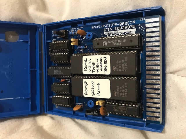 SC-3000 Survivors MEGACART (2018)
I started the original Multicart Project back in 2011, and the Survivors MkII Multicart was released in March 2012. This has been a tribute to a much loved piece of 80s computing history, the wonderful Sega SC-30000 home computer and all the tape software I used as a kid.
This is not and has never been a commercial operation. It is a spare time hobby, and spare time is increasingly hard to find as your kids are growing up.
But every few months another random email would turn up from someone pleading for a multicart to return to their childhood, so I kept things ticking over.
Last year I ran out of the last of the Multicart PCBs and had to decide what to do next.
So I went back and decided to fix some of the things I wasn't happy with in the original design. The result is the new SC-3000 Survivors MEGACART. The four big changes are:
- It now works on the SG-1000 / SG-1000 II / Mark III
- Shifted from 8MBit 27C801 EPROMS to 16MBit 27C160 EPROMs
Give us a Tim Taylor more power grunt! - The reset button to return to the boot menu finally works properly!
- It now takes me twice as long to assemble and test. Oops :)
 SC-3000 Survivors MEGACART (2018)
Getting I/O Port Mapping to work over the SG-1000 / SG-1000 II / Sega Mark III cartridge connector
So how does the magic work? This is a programmer's explanation, so all real Electrical Engineers feel free to scream in horror :)
The basic architecture of the Megacart hasn't changed. It is an incremental improvement to the Multicart memory architecture - you should read how the Mk II SC-3000 Survivors Multicart works.
But instead of 64 slots of 32KB, we now have 128 slots of 32KB available. These slots are accessed by flipping the bits on a SN74LS373 8 bit latch to set the 6 high order bits of the 27C160 EPROMs plus another bit to select between the two 27C160 EPROMS.
That SN74LS373 latch is I/O Port Mapped to the $E0 to $FF range - so you write a value to it like this:
ld a,$ff
out ($e0), a ; select the boot menu ROM / slot
That works great on the Sega SC-3000 because the SC-3000 passes the /IOW signal (Z80 /IORQ strobed with /WR) out the cartridge port on pin B8 so you can tell when it is a port write (rather than a memory write) and therefore update the latch on the Megacart.
But the SG-1000 / II / Mark III don't have pin B8 connected, dammit. So the original Multicart never worked with those.
However it turns out that if you look carefully at the Z80 timing diagrams then you can (reasonably) reliably infer when a port write has occured. Here is the trick:
If the Z80 /WR is low and /MREQ is high, then it is a I/O Port Write, not a memory access
I have included the Z80 timing diagrams below so you can check it out yourself. Assuming those are accurate, then the above statement holds true. So I built a port write detection circuit to implement this rule and see if it would work on a SG-1000. It does.
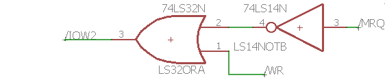
Note that it does not work with a LS04 NOT gate instead of the LS14 Schmitt Trigger NOT gate, so I suspect there are some edge transitions where this statement falls into the undefined category that the LS14 filters out.
Update: I later realized that some of my early inconsistency in results was actually down to faulty or fake chips. In particular I had problems with LS373 chips that were actually HC373s which have CMOS logic voltage level transition points which are different from TTL (and also some bad LS08 and LS14 chips too). The lesson here is to get yourself a cheap IC tester off eBay. That will save you sooooo much time. They work great on simple TTL style logic chips.
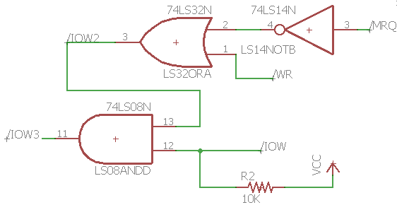
That's great, but it no longer works on a SC-3000. So the second part of the magic is creating a circuit which works on BOTH a SG-1000 and a SC-3000 because you don't want to have to shift a jumper when switching between the two. That gives us this circuit:
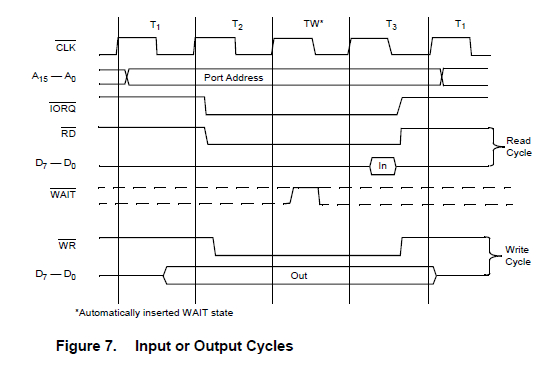 Z80 I/O Timing
On a SC-3000, the /IOW line on cartridge connector pin B8 is the Z80 /IORQ line strobed with the Z80 /WR. But on a SG-1000 pin B8 is not connected.
On a SC-3000, the /MEMW line on cartridge connector pin B6 is the Z80 /MREQ line strobed with the Z80 /WR. But on a SG-1000 pin B6 is just the Z80 /WR signal
So the top half of the circuit (/IOW2) detects an I/O write on a SG-1000, and the bottom half detects an I/O write on a SC-3000
If you are connected to a SG-1000, then the bottom half of the circuit input to the final /IOW3 AND gate is always HIGH because /IOW is not connected so the pullup resistor forces the /IOW3 AND gate input high and the /IOW3 AND result is driven by the top half of the circuit.
 Z80 Memory Read / Write Timing
If you are connected to a SC-3000, then the output of the final /IOW3 AND gate is driven by the bottom half of the circuit (/IOW) because the top half of the circuit (/IOW2) is always HIGH.
That one is a bit harder to explain, but the logic runs like this:
- For /IOW3 to be low, then /IOW2 must also be low
- The only way that /IOW2 can be low is if /MRQ is HIGH AND /MEMW is LOW.
But that isn't possible because... - If this is a memory write then because /MEMW is the Z80 /MREQ strobed with /WR then BOTH /MRQ and /MEMW are low
- If this is an IO write, then /MRQ is high but /MEMW is also high
- If it is an IO read or memory read, then /MRQ is low
- If it is none of the above then both /MRQ is high and /MEMW is high.
- Therefore when attached to a Sega SC-3000, the /IOW2 output is always high
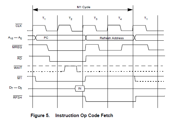 Z80 Instruction Fetch Timing
Ummm... that sounds about right anyway - it has been a few months since I had to think about it :)
Note - this is relying on a pretty accurate Z80 memory timing diagram with no odd little spikes around the Z80 signal transitions. I suspect that if you had a good scope trace you might see some little spikes / transitions around the edges of /IOW3. But in practice it seems to work pretty well and I haven't noticed any issues yet. You can see the Z80 timing charts to the right.
Update: The design actually works really well. See my above comment about getting yourself an IC tester to check the logic chips before you use them. There is only one other issue I have run into. A few SC-3000s don't like the auto-detection circuit. I have a Yeno that it doesn't always work on, and I've had one other report of problems too. So in the later Megacarts I added another jumper J3 which you can remove to disable the SG-1000 part of the detection circuit. That makes the Megacart work on those SC-3000s where the menu system doesn't work reliably. But you MUST have the jumper shunt on J3 for the Megacart to work on a SG-1000 / SG-1000 II / Mark III.
How the Reset Switch works
Just like the Mk II Multicart, the Megacart paging system is divided into 32KB blocks and the 8 bit paging latch swaps those blocks into the lower 32KB of the Z80 memory space from $0000 to $7FFF. The boot menu for the Megacart resides in the top-most 32KB block (block 63 on ROM1, the second 27C160 EPROM).
Side Note: I *really* wish I had used something like a 74LS273 with a reset line to reset all the bits back to zero in the original Multicart design. But I chose the 74LS373 which defaults to all bits ON on startup, and does not have a reset line. Unfortunately I could not change that part out because I would have had to rewrite the custom paging routines I wrote to replace the tape load routines in many of the tape games. So the redesign was stuck with the 74LS373. If you ever build your own cart, choose a paging chip with a reset line that resets to zeros - things are a lot easier and more logical that way :)
Anyway... So a Reset switch has to do two things:
- Swap the boot menu paging block back into memory
- Cause the processor execution to jump to the start of the menu loader
With a couple of TTL logic chips you can swap the boot menu paging block back in. But causing the processor execution to jump to the start of the menu loader is harder. Unfortunately, none of the Sega platforms (SC-3000 / SG-1000 / Mark III) pass the Z80 /RESET line out to the cartridge port. So we need another solution.
The answer is to use the Z80 RST instructions. These are one byte opcodes that cause the Z80 to jump to predefined locations in memory. If you gate one of those values onto the data bus during instruction fetch, then the Z80 will execute that instruction and jump to that memory location.
You can gate a value onto the bus by using a second LS373 latch which is hard coded to output one particular one byte opcode. It is only active while the reset switch on the multicart is depressed. So which opcode to use?
RST $00 is $C7. So if the Z80 sees opcode $C7 it will jump to address $0000
That would have been perfect if I had used a LS273 with a seperate reset line. But I didn't dammit. The only way to update my LS373 paging latch is to gate $FF onto the data bus and get the paging latch to lock onto that.
But lucky lucky me. $FF is also the opcode for RST $38. So my boot menu block has a handler at $0038 to restart the boot menu. So by gating $FF onto the data bus when the reset switch is depressed I both swap the boot block in, and continuously jump to $0038 until I release the switch at which time the boot menu startup code executes.
Note - my first attempt to gate $FF onto the data bus actually used pull up resistors. That worked most of the time, but the reset switch was a little unreliable on the SC-3000 and more unreliable on the SG-1000. I was never sure if that was a real problem or just loose wires on my breadboard. But using a LS373 to gate the opcode onto the data bus is more reliable, and a cleaner solution because it is only active when the reset switch is pressed unlike the pullup resistors.